Contents
实战6:远程访问VPN-L2TP
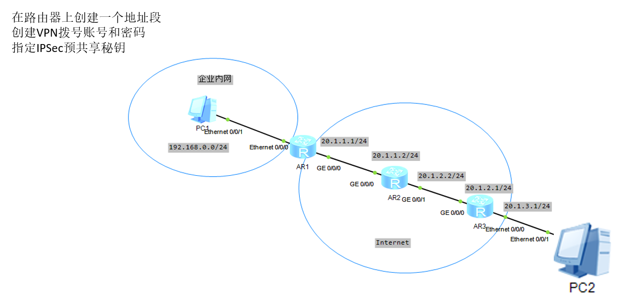
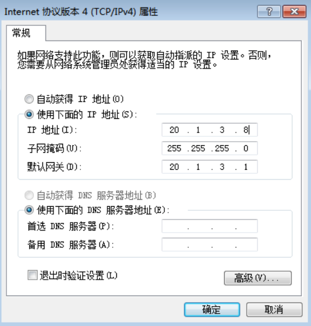
在路由器上创建一个地址段
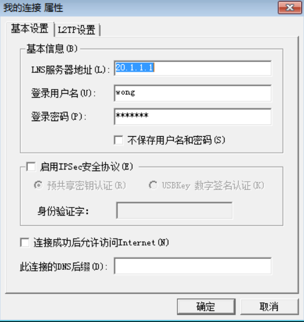
创建VPN拨号账号和密码
指定IPSec预共享秘钥
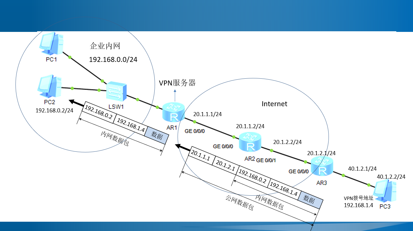
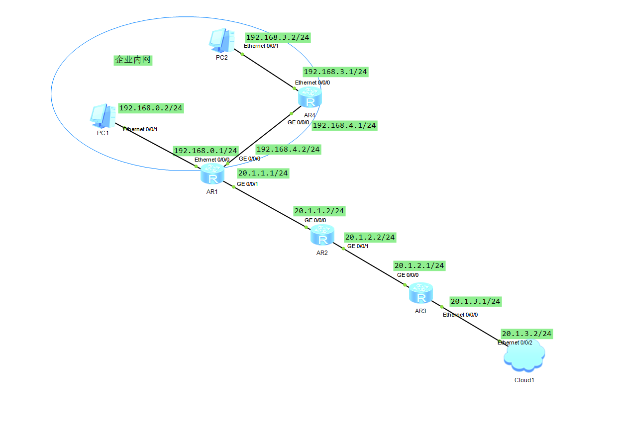
1.拓扑图
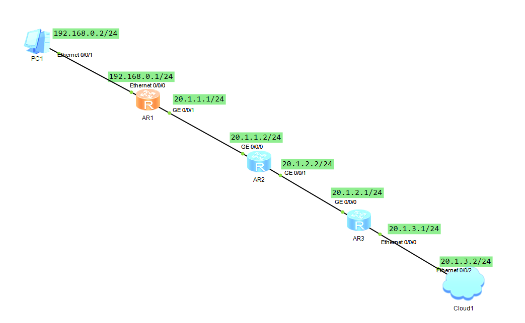
2.环境搭建
R1
[Huawei]sys R1
[R1]int vlanif1
[R1-Vlanif1]ip add 192.168.0.1 24
[R1-Vlanif1]quit

[R1-GigabitEthernet0/0/0]int g0/0/1
[R1-GigabitEthernet0/0/1]ip add 20.1.1.1 24

[R1]ip route-static 20.1.2.0 24 20.1.1.2
[R1]ip route-static 20.1.3.0 24 20.1.1.2
R2
[Huawei]sys R2
[R2]int g0/0/0
[R2-GigabitEthernet0/0/0]ip add 20.1.1.2 24

[R2-GigabitEthernet0/0/0]int g0/0/1
[R2-GigabitEthernet0/0/1]ip add 20.1.2.2 24

[R2]ip route-static 20.1.3.0 24 20.1.2.1
R3
[Huawei]sys R3
[R3]int g0/0/0
[R3-GigabitEthernet0/0/0]ip add 20.1.2.1 24

[R3-GigabitEthernet0/0/0]int vlanif1
[R3-Vlanif1]ip add 20.1.3.1 24

[R3]ip route-static 20.1.1.0 24 20.1.2.2
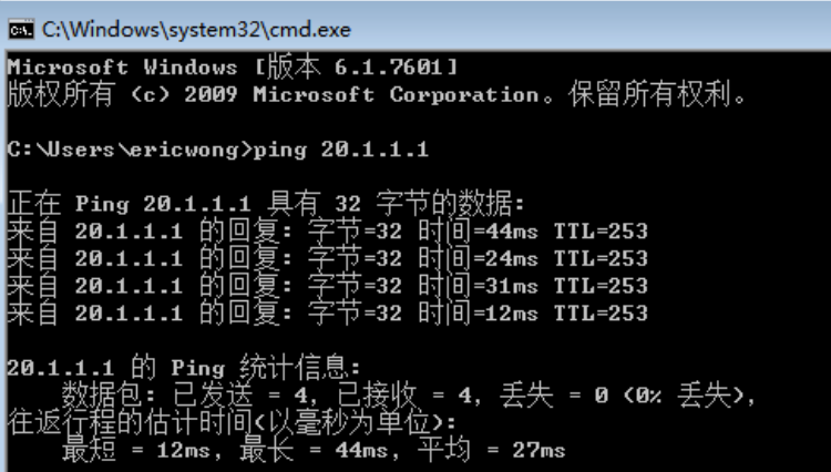
连通性测试
VM-WIN7
3.在公司的路由器上面创建L2TP
<R1>sys
#创建用户
[R1]aaa
[R1-aaa]local-user wong password cipher 91xueit
[R1-aaa]local-user wong service-type ppp
[R1-aaa]quit
#开启L2TP
[R1]l2tp enable
[R1]ip pool lns
[R1-ip-pool-lns]network 192.168.1.0 mask 24
[R1-ip-pool-lns]gateway-list 192.168.1.1
[R1-ip-pool-lns]quit
#建立模板
[R1]interface Virtual-Template 1
[R1-Virtual-Template1]ip address 192.168.1.1 24
[R1-Virtual-Template1]ppp authentication-mode pap
[R1-Virtual-Template1]remote address pool lns
[R1-Virtual-Template1]quit
#建立连接组
[R1]l2tp-group 1
[R1-l2tp1]tunnel authentication
[R1-l2tp1]tunnel password simple huawei
[R1-l2tp1]allow l2tp virtual-template 1
[R1-l2tp1]quit
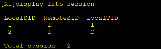
#查看建立连接情况
display l2tp session
有用户成功连接的显示如下
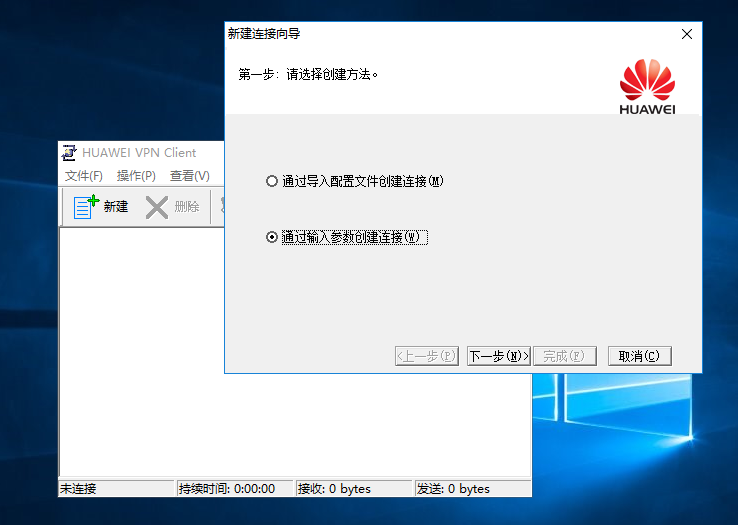
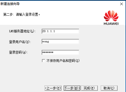
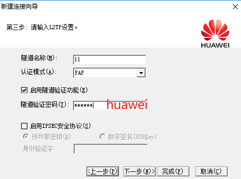
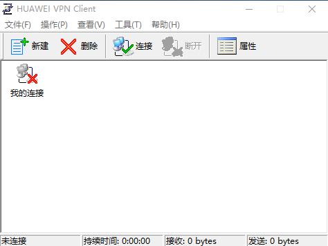
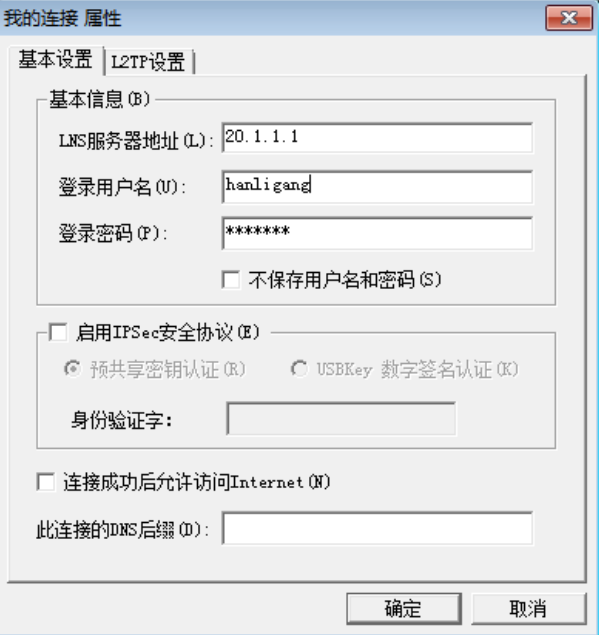
4.安装HUAWEI-VPN-CLIENT
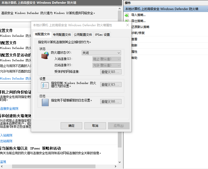
关闭防火墙
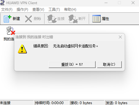
拨号不成功,显示“错误愿意:无法启动虚拟网卡适配任务”,出现这个原因很可能是因为用了,WIN7以上的系统,HUAWEI VPN CLIENT目前只适用于WIN7及其以下系统
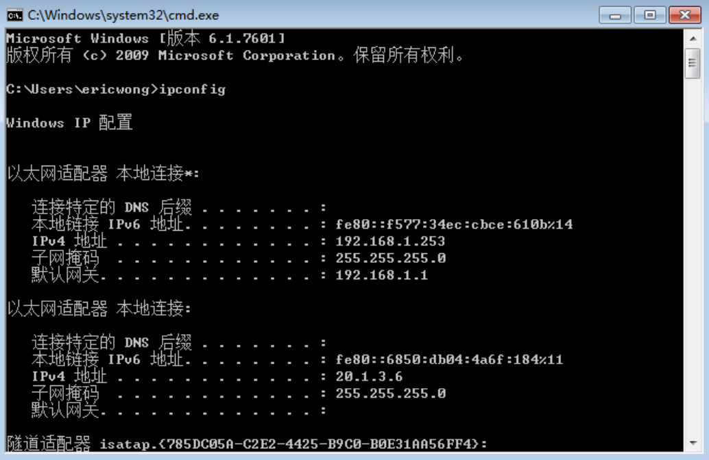
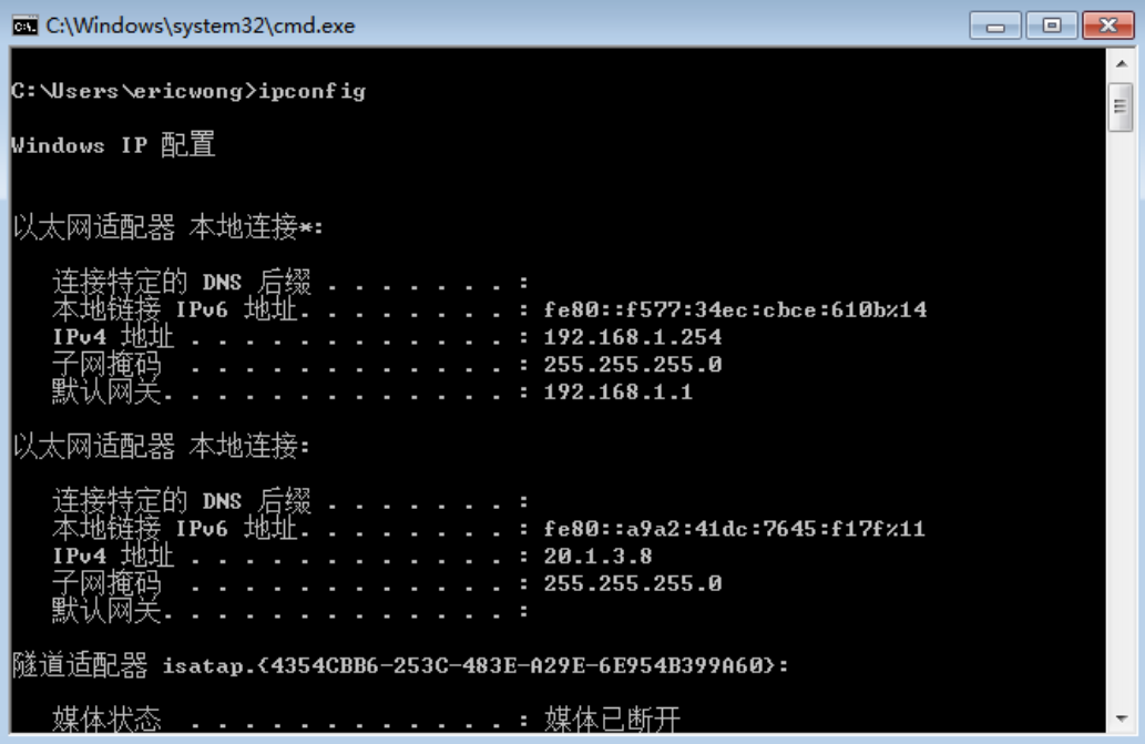
5.成功连接
会自动分配一个1.0网段的地址
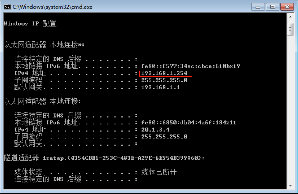
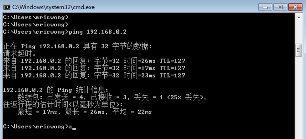
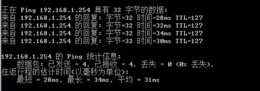
同时可以PING通内网地址
6.增加一台异地设备,可以通过公司的拨号,形成组网
WIN7-1
WIN7-2
测试
7.实现访问内网其他网段
R4
<Huawei>sys
Enter system view, return user view with Ctrl+Z.
[Huawei]sys R4
[R4]int vlanif1
Jul  8 2025 17:18:39-08:00 R4 %%01IFNET/4/IF_STATE(l)[0]:Interface Vlanif1 has t
urned into UP state.
[R4-Vlanif1]ip add 192.168.3.1 24
Jul  8 2025 17:18:47-08:00 R4 %%01IFNET/4/LINK_STATE(l)[1]:The line protocol IP
on the interface Vlanif1 has entered the UP state.
[R4-Vlanif1]int g0/0/0
[R4-GigabitEthernet0/0/0]ip add 192.168.4.1 24
Jul  8 2025 17:19:14-08:00 R4 %%01IFNET/4/LINK_STATE(l)[2]:The line protocol IP
on the interface GigabitEthernet0/0/0 has entered the UP state.
[R4-GigabitEthernet0/0/0]quit
[R4]ip route-st
[R4]ip route-st
[R4]ip route-static 192.168.0.0 24 192.168.4.2
[R4]ip route-static 192.168.1.0 24 192.168.4.2
<R1>SYS
Enter system view, return user view with Ctrl+Z.
[R1]int g0/0/0
[R1-GigabitEthernet0/0/0]ip add 192.168.4.2 24
Jul  8 2025 17:21:25-08:00 R1 %%01IFNET/4/LINK_STATE(l)[0]:The line protocol IP
on the interface GigabitEthernet0/0/0 has entered the UP state.
[R1-GigabitEthernet0/0/0]quit
[R1]ip route-st
[R1]ip route-static 192.168.3.0 24 192.168.4.1
测试
PC1 PING PC2
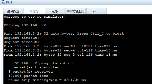
WIN7 PING PC2(成功拨号情况下)
